Introduction to CAD
1.1 – What CAD Software Is?
CAD = Computer-Aided Design.
It helps engineers create exact digital models of real parts and machines.
Going deeper:
🔍 CAD is more than just drawing
It allows engineers to:
- Build 3D models with real dimensions
- Add material properties (steel, aluminum, plastic, etc.)
- Calculate mass, volume, center of gravity
- Simulate movement, stress, heat, fluid flow
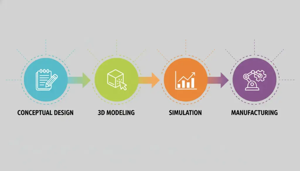
- Prepare files for CNC machining & 3D printing
🔧 Why this matters:
Without CAD, engineers would have to rely on:
- Manual sketches
- Physical prototypes
- Trial and error
CAD removes most of that by putting the “prototype” inside the computer.
1.2 – How CAD Transformed Mechanical Engineering
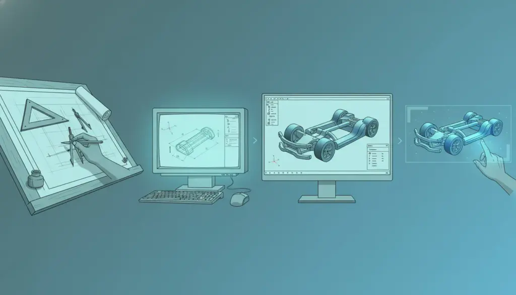
Before CAD, everything was manual:
- Drawings took hours or days
- Editing meant erasing and redrawing
- Sharing drawings required physical copies
- Mistakes were common
- Large assemblies were extremely difficult to visualize
📌 CAD solved these problems with major innovations:
A. Digital Accuracy
CAD can measure down to fractions of a millimeter.
Dimensions are controlled by math, not human hand-drawing.
B. 3D Visualization
Engineers can now:
- Rotate the model
- Cut sections
- Explode assemblies
- See how parts interact
This improved understanding dramatically.
C. Parametric Editing
Change one dimension → the entire model updates.
Example:
If a plate thickness changes from 5 mm to 8 mm, holes and related features adjust automatically if they’re constrained.
D. Simulation Built In
Engineers can test designs without manufacturing:
- Stress
- Vibration
- Temperature
- Flow
- Movement
This reduces costly mistakes.
E. Digital Collaboration
Teams can work on the same design from different cities or countries.
1.3 – Why CAD Is Essential Today
A. Precision Manufacturing
Modern industries require extreme accuracy:
- Aerospace
- Automotive
- Medical devices
CAD lets you design with tolerances like ±0.01 mm.
B. Faster Product Development
Because CAD allows:
- Quick edits
- Reusing older designs
- Automatic drawing creation
- Instant calculations
Products can be developed much faster.
C. Reduced Cost
CAD cuts costs by removing:
- Many physical prototypes
- Wasted materials
- Repeated manufacturing test cycles
D. Better Communication
CAD models can be shared as:
- Drawings
- Animations
- 3D interactive files
- PDFs
- STEP/IGES files
This helps designers, machinists, and clients understand the design clearly.
E. Direct Link to Manufacturing
CAD files can be exported directly to:
- CNC machines
- 3D printers
- Laser cutters
- CAM software
This makes the workflow smooth and error-free.
Evolution of CAD in Mechanical Engineering
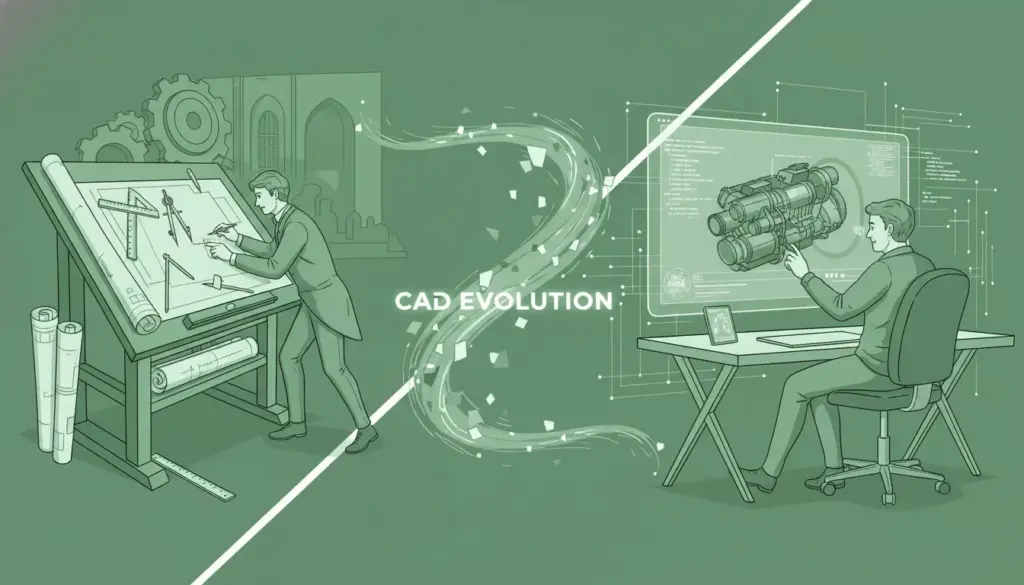
CAD has gone through four major stages over the past 60+ years.
Let’s break each one down clearly.
2.1 – Early 2D CAD Systems (1960s–1980s)
This was the first generation of CAD.
🖥️ What early CAD looked like
- Only 2D lines and shapes
- No 3D
- No parametric tools
- No simulation
- No automatic updates
- Hardware was massive and expensive
🎯 Purpose at that time
Early CAD simply tried to replace the drawing board.
Engineers used CAD to:
- Draw mechanical parts
- Create top, front, and side views
- Generate technical drawings faster
⚠️ Limitations
- Hard to understand complex parts
- Difficult to imagine how pieces fit together
- Changing one view meant manually updating all views
- Time-consuming, especially for assemblies
Even though basic, early CAD was a huge improvement over pencil and paper.
2.2 – Shift to 3D & Parametric Modeling (1990s–2010s)
This phase revolutionized engineering.
🔵 Step 1: 3D Modeling
CAD moved into true 3D.
Engineers could now create:
- 3D solid models
- Assemblies
- Realistic visualizations
- Section views easily
Why 3D was a breakthrough:
- Engineers could see the part exactly as it would look in real life
- Detect assembly issues early
- Communicate designs better
🔵 Step 2: Parametric Modeling
This was the most important innovation.
What is parametric?
Parts are controlled by dimensions and rules.
Example:
If a hole must stay 15 mm from the edge, the hole stays 15 mm even if you change the plate size.
Why parametric CAD changed everything
- Super fast editing
- Automatic updates
- Error reduction
- Very clean design history
- Massive time savings
Traditional tools like SolidWorks, Inventor, Creo became industry standards here.
This era made CAD extremely powerful.
2.3 – Modern Simulation & Analysis Tools (2010s–Present)
CAD grew into a complete engineering environment.
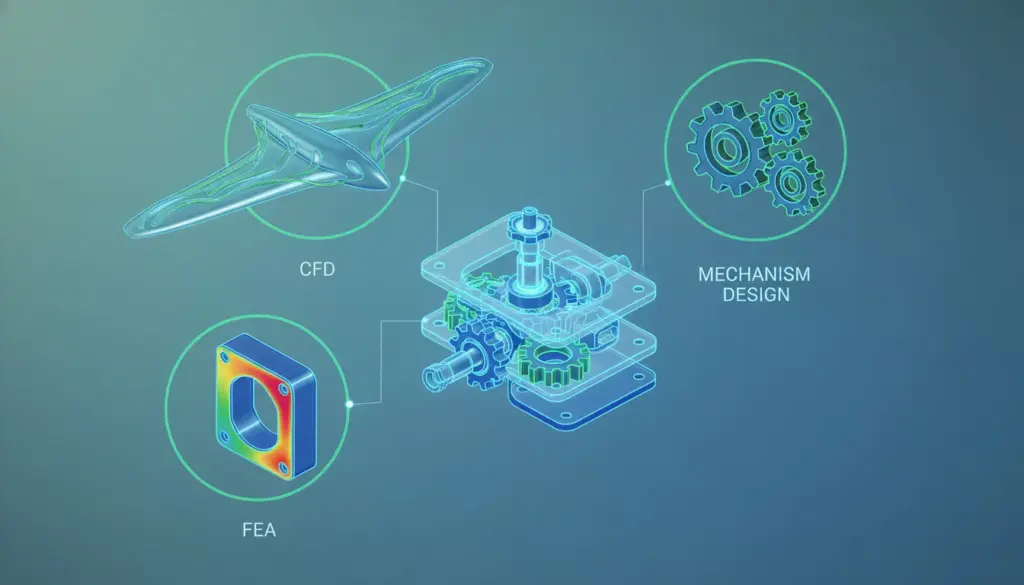
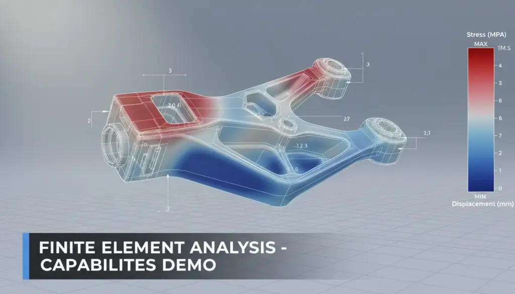
A. FEA – Finite Element Analysis
Engineers can test:
- Stress
- Deformation
- Safety factors
- Heat
- Vibration
All inside CAD, before manufacturing anything.
B. CFD – Computational Fluid Dynamics
Engineers can simulate:
- Airflow
- Cooling
- Pressure
- Drag
- Aerodynamics
Used in:
- Automotive
- Aerospace
- HVAC
- Electronics cooling
C. Motion Simulation
CAD can simulate:
- Gear trains
- Linkages
- Robot arms
- Piston motion
Engineers can check if the mechanism works physically.
2.4 – Rise of Cloud CAD (2015–Present)
This is the newest evolution.
Cloud CAD introduced:
- Real-time collaboration
- Browser-based CAD
- Automatic version control
- Cloud storage
- CAD on laptops/tablets
- Integrated CAD + CAM + CAE
Examples:
- PTC Onshape
- Autodesk Fusion 360
Why cloud CAD matters today:
- Teams work remotely
- Students need affordable tools
- Companies want faster design cycles
- Automatic updates save IT time
This is where the future of CAD is heading.

Key Benefits of CAD
CAD has many benefits, but we will explore them one by one in a clear, simple, deeper way.
3.1 – Accuracy and Precision
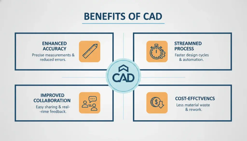
CAD allows you to design with extreme accuracy, far beyond what hand drawings can achieve.
Why accuracy matters
A mistake of even 0.5 mm can cause:
- Misaligned parts
- Assembly failures
- Manufacturing defects
How CAD ensures accuracy
CAD uses:
- Exact dimensions (0.01 mm or better)
- Constraints
- Mathematical geometry
- Automatic detection of overlapping parts
- Tolerance controls (GD&T)
Example:
If two holes must be perfectly aligned in two different plates, CAD guarantees they stay aligned even after modifications.
3.2 – Faster and Easier Design Process
CAD speeds up the workflow massively.
Why?
Because CAD allows:
- Parametric updates
- Feature history
- Copying/duplicating features
- Instant previews
- Automatic drawing generation
Example:
Changing the length of a part from 100 mm to 120 mm updates
- holes
- cuts
- fillets
- chamfers
- mating features
automatically.
This saves hours or days of manual rework.
3.3 – Collaboration and Communication
In modern engineering, teams rarely work alone.
CAD supports:
- Sharing models instantly
- Creating 3D PDFs
- Cloud-based real-time editing
- Commenting tools
- Version control
- Compatible file formats (STEP, IGES, STL)
This improves teamwork between:
- Designers
- Engineers
- Machinists
- Clients
- Manufacturers
Example:
A machinist can see the 3D model to avoid misunderstandings about a drawing.
3.4 – Cost Savings & Rapid Prototyping
How CAD reduces cost:
- Fewer physical prototypes
Because CAD can simulate, test, and predict failures before manufacturing. - Less material waste
Virtual testing prevents mistakes during machining. - Shorter development time
Faster designs = more projects completed. - Better manufacturability
CAD supports DFM (Design for Manufacturing), avoiding expensive mistakes.
Rapid Prototyping
CAD models directly convert to:
- 3D printable files (STL)
- CNC machining toolpaths (through CAM)
This allows engineers to create prototypes in hours instead of weeks.
3.5 – Simulation and Virtual Testing
Simulation is one of CAD’s biggest strengths today.
Types of simulations in CAD:
- FEA → Strength, stress, deformation
- CFD → Airflow and fluid behavior
- Thermal → Heat transfer
- Motion → Mechanism movement
- Modal → Vibration and natural frequencies
Why simulation is important:
- Prevents design failures
- Reduces number of physical tests
- Ensures safety
- Helps choose the right materials
- Cuts manufacturing costs
Example:
Instead of making 5 prototypes to test strength, engineers can simulate 50 scenarios in CAD within minutes.
Core MCAD Principles & Applications
MCAD = Mechanical Computer-Aided Design
It focuses on designing mechanical components and systems.
We’ll go through each sub-topic step by step.
4.1 – 2D & 3D Modeling Basics
2D Modeling
2D is the foundation.
It includes:
- Lines
- Arcs
- Circles
- Dimensions
- Technical drawings
2D is used for:
- Manufacturing drawings
- Schematics
- Flat layouts
- Laser cutting / plasma cutting designs
But 2D alone cannot fully show the shape of a part.
3D Modeling
3D modeling represents the actual shape of an object.
Types of 3D objects:
- Blocks
- Cylinders
- Extrusions
- Revolves
- Sweeps
- Lofts
3D makes it easy to:
- Visualize
- Assemble
- Test
- Manufacture
Why 3D is essential:
- You can check fit and clearances
- You can run simulations
- You can generate drawings automatically
- You can avoid design mistakes early
3D is the modern “language” of engineering.
4.2 – Parametric, Solid, and Surface Modeling
A. Parametric Modeling
This is the heart of modern CAD.
A parametric model has:
- Dimensions
- Constraints
- Equations
- Design intent
Example:
Two holes must stay 20 mm apart → even if the part grows.
This makes design updates fast and consistent.
B. Solid Modeling
Solid models have:
- Volume
- Mass
- Density
- Center of gravity
Solids are used for:
- Mechanical parts
- Assemblies
- Machining
- FEA simulations
Example:
A gearbox housing, engine block, robot arm part.
Solid modeling ensures the part behaves like a real-world physical object.
C. Surface Modeling
Surfaces are thin “skins” with no thickness.
Used for:
- Aerodynamic shapes
- Car bodies
- Aircraft wings
- Consumer products (phones, bottles)
Surface modeling allows:
- Smooth curves
- Complex geometry
- Organic shapes
It’s used heavily in aerospace, automotive, and product design.
4.3 – FEA & CFD Analysis
Simulation is a core part of MCAD.
A. FEA – Finite Element Analysis
FEA divides a part into tiny elements (mesh) and calculates:
- Stress
- Strain
- Deformation
- Safety factor
Why FEA is important:
- Prevents failures
- Helps choose materials
- Reduces prototype cost
- Ensures safety
Example:
Testing if a bracket breaks under 500 N force.
B. CFD – Computational Fluid Dynamics
CFD simulates flow of air or liquid around or inside a part.
Used for:
- Aerodynamics
- Cooling
- Pipe flow
- HVAC systems
- Turbomachinery
CFD can show:
- Pressure
- Velocity
- Temperature
- Turbulence
Example:
Simulating airflow around a car to reduce drag.
4.4 – Mechanism Design & Motion Simulation
This part focuses on moving mechanical systems.
CAD can simulate:
- Gears
- Cams
- Linkages
- Piston systems
- Suspension
- Robot arms
What motion simulation checks:
- Does the mechanism move correctly?
- Are there collisions?
- Are the joints constrained properly?
- Are forces balanced?
This helps engineers test motion before making physical prototypes.
Examples:
- Testing a robot arm’s reach
- Simulating a gear train
- Checking if a crankshaft rotates smoothly
Traditional Desktop-Based Parametric CAD
Traditional CAD includes tools like:
- SolidWorks
- PTC Creo
- Autodesk Inventor
- CATIA
- Siemens NX
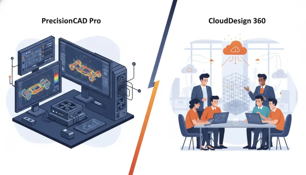
These programs run on powerful local computers, not browsers or cloud servers.
Let’s break down each sub-topic.
5.1 – What It Is & How It Works
Traditional CAD is installed on a workstation.
All processing happens locally on your computer.
✔ Advantages of local processing:
- Very fast when you have strong hardware
- Handles extremely large assemblies
- Works offline
- Stable environment for years
✔ Why industries still rely on it:
Because manufacturing companies value:
- Stability
- Precision
- Deep engineering tools
- Proven reliability
Traditional CAD has existed and matured for 20+ years, so companies trust it.
5.2 – Main Features
Traditional CAD is extremely powerful.
Here are the key features explained simply:
A. Powerful 3D Parametric Modeling
This is the core.
You can build:
- Extrusions
- Revolves
- Sweeps
- Lofts
- Patterns
All fully controlled by:
- Sketch dimensions
- Constraints
- Relations
- Equations
Industrial design depends heavily on this power.
B. Integrated or Add-On FEA/CFD
Traditional CAD offers strong simulation tools:
- Stress analysis
- Vibration analysis
- Heat transfer
- Fluid flow
Because processing is local, it can handle:
- Very fine mesh
- Large models
- Complex analysis
C. CAM Tools
Many traditional CAD systems connect to CAM:
- CNC machining
- Toolpath generation
- Manufacturing preparation
SolidWorks, for example, has SW CAM.
D. Detailed Drafting & GD&T
Traditional CAD has:
- Advanced dimension tools
- Tolerancing
- Symbols
- Section views
- BOM generation
Manufacturing heavily depends on these.
E. PLM / PDM Integration
Traditional CAD often connects to:
- Windchill
- Teamcenter
- Vault
- ENOVIA
These systems manage:
- File versions
- Revisions
- Access control
This is critical in industries like aerospace or automotive.
5.3 – Ideal Users & Strengths
✔ Ideal for:
- Large companies
- Heavy engineering (automotive, aerospace, industrial machinery)
- R&D centers
- Teams working with big assemblies
- Industries requiring strong data security
Strengths Explained
A. High Performance
With a powerful workstation:
- 10,000+ part assemblies
- Complex simulations
- Detailed modeling
run smoothly.
B. Deep Feature Set
Traditional CAD has 20+ years of development.
It supports:
- Special surfaces
- Weldments
- Sheet metal
- Electrical routing
- Complex assemblies
- Mold design
- Advanced simulation
Cloud CAD is still catching up.
C. Industry Acceptance
Most manufacturers worldwide accept:
- SolidWorks files
- Creo files
- CATIA files
This makes collaboration easy.
D. Local Data = Controlled Security
Companies in defense, aerospace, or government prefer local storage.
5.4 – Limitations
Despite its power, traditional CAD has real drawbacks.
A. Very High Cost
You must buy:
- Workstation hardware ($1500–$6000)
- Software license ($4000–$8000)
- Annual maintenance (~$1500/year)
This is expensive for students and startups.
B. Collaboration Challenges
Sharing files means:
- Emailing
- Using USB drives
- Checking files in/out
- Conflicts with file versions
Cloud CAD solves this with real-time editing.
C. Harder Learning Curve
Traditional interfaces are:
- Older
- Complex
- Packed with many features
Beginners often feel overwhelmed.
D. Difficult Updates
Each workstation must be updated manually.
Sometimes updates require:
- IT support
- Re-installation
- Downtime
E. Tied to One Device
You can only work on the machine where it is installed.
No mobile access.
Modern Cloud-Based Integrated CAD
Cloud CAD includes tools like:
- PTC Onshape
- Autodesk Fusion 360
- Siemens NX Cloud (emerging)
These tools run in the cloud, not just on a local computer.
Let’s explore each part in detail.
6.1 – What Makes Cloud CAD Different
Cloud CAD does not rely on your computer’s hardware.
Instead, it uses:
- Cloud servers
- Browser interface
- Online storage
✔ This means:
- No installation
- No manual updates
- No need for a high-end workstation
- Access anywhere with internet
- Real-time teamwork
You can run Cloud CAD on:
- A laptop
- A tablet
- A phone
- A low-end PC
- Even a Chromebook
Your hardware does not limit the CAD performance.

6.2 – Main Features
A. Integrated CAD + CAM + CAE + PDM
Cloud CAD combines everything into one platform:
- 3D CAD modeling
- FEA (stress analysis)
- CAM (CNC toolpaths)
- Rendering
- Assembly simulation
- Data management (PDM)
- Version control
Traditional CAD often needs multiple expensive add-ons, but cloud CAD offers many tools in a simpler package.
B. Real-Time Multi-User Collaboration
This is the biggest advantage.
Just like Google Docs → multiple people can work on the same document at the same time.
Cloud CAD allows:
- Multiple engineers editing the same model
- Live updating
- Tracking who changed what
- Comments directly on the model
- Branching and merging designs
This eliminates:
- Emailing files
- Version conflicts
- Lost data
- “File is locked by another user” errors
C. Automatic Version Control & History
Every change you make is saved as a timeline entry.
You can:
- Revert to older versions
- Compare two versions
- Create branches
- Merge designs
- Track full design life-cycle
No more:
- “Final_Design_v16_last_final_final.stp”
- Confusion with file naming
- Overwriting mistakes
D. Accessibility from Any Device
Because everything runs in the cloud, you can:
- Model on a tablet
- View models on your phone
- Check designs on a laptop
- Work from home, office, or anywhere
This flexibility is perfect for:
- Remote teams
- Students
- Global companies
E. Generative Design & Additive Manufacturing
Cloud CAD platforms often have built-in tools for:
- Topology optimization
- Lightweighting
- Lattice structures
- Direct export to 3D printing
This is extremely useful for:
- Aerospace
- Robotics
- Automotive electric vehicles (EVs)
6.3 – Ideal Users & Strengths
✔ Ideal for:
- Students
- Small to medium businesses
- Startups
- Makers
- Remote teams
- Schools and universities
- Companies wanting fast development cycles
Strengths Explained
A. Lower Cost
You don’t need:
- Expensive workstation
- Expensive license
Cloud CAD uses subscription pricing.
B. Ease of Use
Modern interfaces are:
- Cleaner
- Simpler
- Easier for beginners
- More intuitive than older CAD systems
C. Seamless Updates
Cloud CAD updates automatically:
- No installation
- No maintenance
- No downtime
You always have the latest version.
D. Strong Collaboration Tools
Ideal for teams working in different locations or time zones.
E. Integrated Workflows
Because everything is in one place, you avoid switching between:
- CAD
- CAM
- Simulation
- PDM software
This saves time and prevents errors.
6.4 – Limitations
Even though cloud CAD is powerful, it has limitations.
A. Requires Stable Internet
You must be connected almost all the time.
Poor internet = poor performance.
B. Not Ideal for Extremely Large Assemblies
Cloud servers may struggle with:
- 10,000+ part assemblies
- Heavy automotive or aerospace models
Traditional CAD handles massive assemblies better.
C. Data Security Concerns
Some companies worry about storing designs in the cloud, especially:
- Defense
- Aerospace
- Government projects
Although cloud CAD companies follow strict security standards, some organizations still prefer local control.
D. Vendor Dependence
If the server is down, you cannot access:
- Files
- Projects
- Work
Traditional CAD does not have this risk.
Choosing the Right CAD & Future Trends
We will go through:
- Traditional vs Cloud → Who wins where
- Best CAD choice for different users
- Future technologies that will change CAD forever
Let’s go step by step.
7.1 – Traditional vs. Cloud CAD: Who Wins Where?
There is no universal “best” CAD.
Each system is best for specific conditions.
Let’s compare deeply but simply.
A. Performance (Who Wins: Traditional CAD)
Traditional CAD uses your local hardware.
A powerful workstation → extreme performance.
Best for:
- Large assemblies (10,000+ parts)
- Heavy simulations
- Complex surface models
- Automotive, aerospace, industrial machinery
Cloud CAD is improving but still limited for huge models.
B. Collaboration (Who Wins: Cloud CAD)
Cloud CAD gives real-time teamwork.
Like Google Docs → multiple engineers editing the same model at once.
Traditional CAD requires:
- File transfers
- PDM check-in / check-out
- Slow collaboration
Cloud CAD completely wins here.
C. Accessibility (Who Wins: Cloud CAD)
Traditional CAD = one computer only
Cloud CAD = browser + tablet + phone + laptop
Work anywhere with internet.
D. Cost (Who Wins: Cloud CAD)
Traditional CAD →
- High cost (software + workstation + maintenance)
Cloud CAD → - Low initial cost
- Subscription-based
- No expensive hardware
Startups and students benefit greatly.
E. Feature Depth (Who Wins: Traditional CAD)
Traditional CAD has 20+ years of development.
It has:
- Super advanced surfacing
- Deep simulation tools
- Industry-specific modules
- Complex assembly tools
Cloud CAD is growing fast but not fully equal yet.
F. Security (Who Wins: Traditional CAD)
Some industries must keep data local:
- Defense
- Military
- Government
- High-security manufacturing
They prefer traditional CAD stored on secure servers.
Final Judgement
👉 Traditional CAD wins in performance, depth, and security.
👉 Cloud CAD wins in collaboration, accessibility, cost, and speed of workflow.
Both have different strengths.
7.2 – Best CAD Type for Different Users
Let’s match the CAD type to the user.
A. Students
Best: Cloud CAD
Why:
- Free/cheap
- Easy to learn
- Runs on any device
- All-in-one tools
Fusion 360 and Onshape are very popular for students.
B. Startups
Best: Cloud CAD
Why:
- Low cost
- Fast teamwork
- Quick prototyping
- No IT needed
Startups need speed → cloud wins.
C. Small/Medium Businesses (SMBs)
Best: Cloud CAD or Hybrid
Depends on:
- Budget
- Team size
- Collaboration needs
Many SMBs use Fusion 360 for everything.
D. Large Enterprises
Best: Traditional CAD
Why:
- Deep features
- Very large assemblies
- Strict data control
- Stable hardware environment
They often use CATIA, Creo, NX, or SolidWorks.
E. Remote Teams
Best: Cloud CAD
Why:
- Real-time collaboration
- Access anywhere
- No file transferring
Perfect for modern global teams.
F. High-Security Industries
Best: Traditional CAD (Local Storage)
Examples:
- Aerospace
- Defense
- Weapons
- Government research
They avoid the cloud due to security concerns.
7.3 – The Future of CAD
CAD is evolving very quickly.
Here are the major future trends explained clearly.

A. AI & Machine Learning
AI will help:
- Auto-generate designs
- Suggest improvements
- Detect design mistakes
- Optimize shapes
- Speed up modeling
- Automate repetitive tasks
AI design copilots are already appearing.
B. Generative Design
Instead of designing manually, you tell the computer:
- Load
- Material
- Cost
- Weight limits
And the computer generates many optimized shapes.
This will change:
- Aerospace
- Robotics
- Automotive lightweight parts
C. VR & AR in CAD
Immersive technologies allow engineers to:
- Walk inside an assembly
- View parts in real scale
- Interact with the design in 3D space
This helps with:
- Design reviews
- Training
- Collaboration
D. Cloud Growth
More companies will move to:
- Browser-based CAD
- Real-time collaboration
- Global design teams
- Automatic version control
This is the direction the industry is heading.
E. IoT Integration
Smart products send real-time data back to CAD.
Engineers can:
- Adjust designs based on sensor data
- Predict failures
- Improve performance
- Understand real usage conditions
This is called Model-Based Design.
