Imagine you want to cut a very hard piece of metal. Usually, you would use a saw or a drill. But what if the metal is so hard that it breaks your drill?
This is where Electrochemical Machining (ECM) comes in. It is a way to cut metal without ever touching it! It uses electricity and salty water to dissolve the metal, shape it, and polish it all at once.
Think of it like “reverse electroplating.” Instead of adding gold to a ring, we are taking metal away to make a shape.
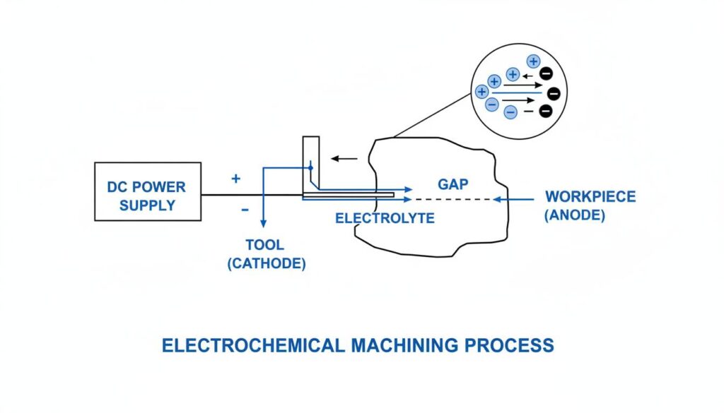
Technical Diagram: A real world application of the Electrochemical Machining (ECM) process. Show a DC power supply connected to a tool (cathode) and a workpiece (anode). Show liquid flowing between them labeled ‘Electrolyte’.
Requirements of Tool Material for ECM
In ECM, the “tool” is the part that shapes the metal. We call the tool the Cathode (negative side). The metal we are cutting is the Anode (positive side).
Because the tool does not touch the metal, it does not wear out like a drill bit. However, it must have special qualities to work correctly.
1. High Electrical Conductivity
The tool acts like a wire. It must let electricity flow through it very easily. If the tool resists electricity, it will get hot and waste energy.
2. High Chemical Resistance
We use strong salty water or acids (electrolytes) in this process. The tool sits in this liquid all the time. The tool material must not rust or dissolve. If the tool dissolves, we lose the shape we are trying to make.
3. High Stiffness
Even though the tool doesn’t touch the metal, the liquid flows very fast. It flows like a fire hose! The tool must be stiff and strong so the rushing water doesn’t bend it.
4. High Thermal Conductivity
Electricity creates heat. The tool needs to be able to move that heat away quickly. If it holds onto the heat, it might warp or melt.
5. Easy to Machine
We need to shape the tool first. If we want to cut a square hole, we need a square tool. The material should be easy for us to shape into whatever form we need.
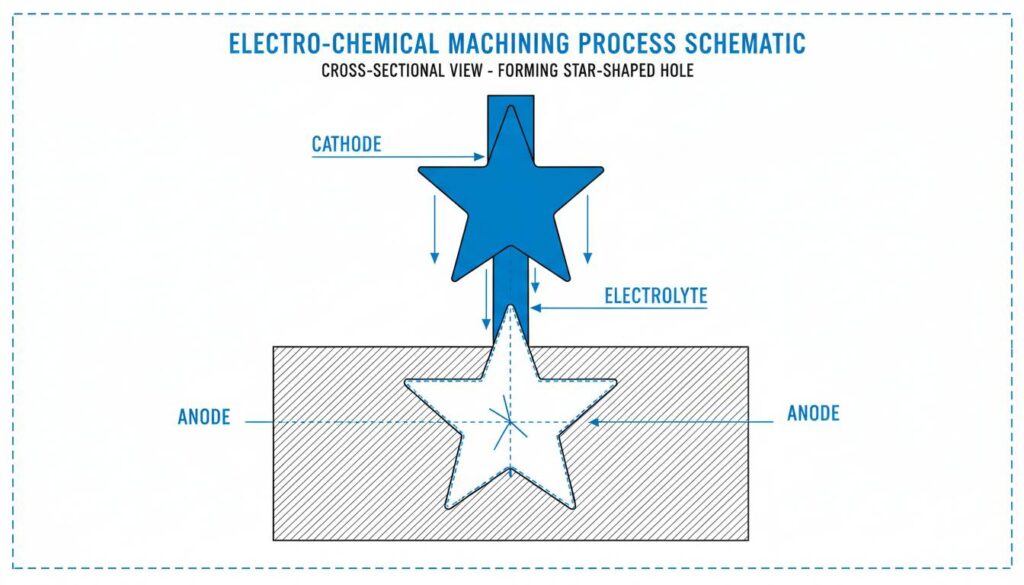
Technical Diagram: A close-up cross-section illustration showing a shaped tool (cathode) lowering into a metal workpiece (anode). The tool has a specific shape, like a star or hexagon, and the hole being formed matches that shape perfectly.
Think About It:
If the tool material had low electrical conductivity (like wood or plastic), would the ECM process work? Why or why not?
Commonly Used Tool Materials
Based on the requirements above, we choose materials that are good conductors and don’t rust easily. Here are the most common ones:
Copper
Copper is the champion of electricity. It conducts current better than almost anything else. It is also soft enough to shape easily.
- Best for: General purpose cutting.
Brass
Brass is a mix of Copper and Zinc. It is very easy to machine (cut into shapes). It doesn’t conduct electricity as well as pure copper, but it is stronger.
- Best for: Tools that need complex shapes.
Stainless Steel
Stainless steel is very strong and resists rust (corrosion) very well. It is stiffer than copper.
- Best for: When the electrolyte liquid is very corrosive (acidic).
Titanium
Titanium is super strong and very light. It is extremely resistant to chemicals.
- Best for: Very specialized, high-precision jobs.
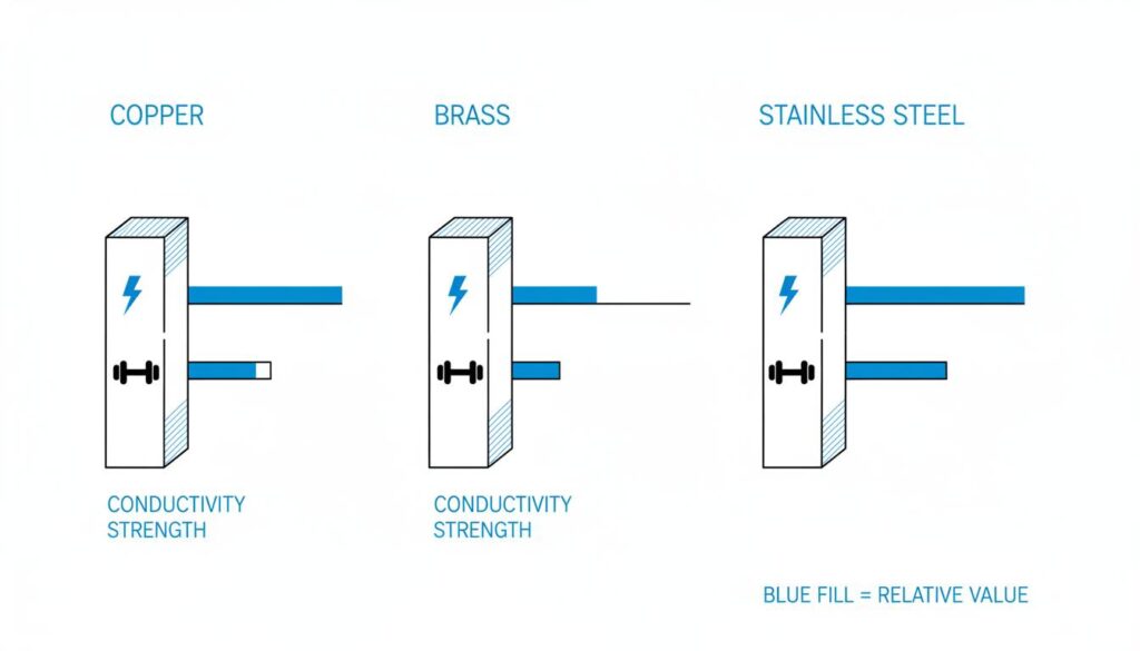
Technical Diagram: A technical comparison chart showing bars of Copper, Brass, and Stainless Steel. Next to each bar, show symbols representing ‘Conductivity’ (lightning bolt) and ‘Strength’ (dumbbell).
Quick Quiz:
If you needed to make a tool with a very tiny, complicated shape, would you choose Brass or Stainless Steel? (Hint: Look at which one is easier to machine).
The Electrolyte Used in ECM
The electrolyte is the liquid that flows between the tool and the metal. It is the “secret sauce” of ECM.
What does the Electrolyte do?
- Completes the Circuit: It acts like a bridge for the electricity to travel from the tool to the metal.
- Removes Waste: As the metal dissolves, it turns into sludge. The flowing liquid washes this sludge away.
- Cools it Down: It takes away the heat generated by the electricity.
Common Electrolytes
We usually use salt solutions mixed with water.
- Sodium Chloride (NaCl): This is basically table salt and water. It is cheap and conducts electricity well.
- Sodium Nitrate (NaNO3): This is another type of salt. It is better for making very precise cuts because it doesn’t let the electricity spread out too much.
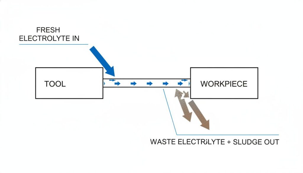
Technical Diagram: A diagram showing the flow of electrolyte. Blue arrows show fresh electrolyte entering the gap between the tool and workpiece. Brown/Grey arrows show the ‘sludge’ or waste material exiting the gap.
Process Parameters of Electro Chemical Machining
To get a perfect cut, an engineer has to adjust the “knobs” on the machine. These settings are called Process Parameters.
1. Voltage (The Push)
This is the force pushing the electricity.
- Typical Range: Low voltage, usually 10 to 20 Volts.
- Why? We don’t need high voltage to create sparks (like welding). We just need a steady flow to dissolve the metal chemically.
2. Current (The Flow)
This is the amount of electricity flowing.
- Typical Range: Very High! It can be 50 to 40,000 Amps.
- Rule: The higher the current, the faster the metal is removed. More current = Faster cutting.
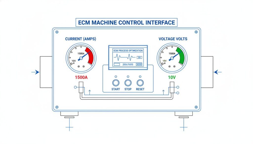
Technical Diagram: A control panel visualization for an ECM machine. Highlight a gauge labeled ‘Current (Amps)’ pointing to a high number (red zone) and a gauge labeled ‘Voltage (Volts)’ pointing to a low number (green zone).
3. Feed Rate (The Speed)
This is how fast we push the tool toward the metal.
- The Balance: If you push too fast, the tool might touch the metal (Short Circuit!). If you push too slow, the cut takes forever.
- Typical Speed: 0.5 mm to 15 mm per minute.
4. Inter-electrode Gap (The Space)
This is the distance between the tool and the metal workpiece.
- The Gap: It is tiny! Usually 0.1 mm to 0.6 mm.
- Why? A smaller gap makes the cut more accurate. If the gap is too big, the electricity spreads out and makes a messy hole.
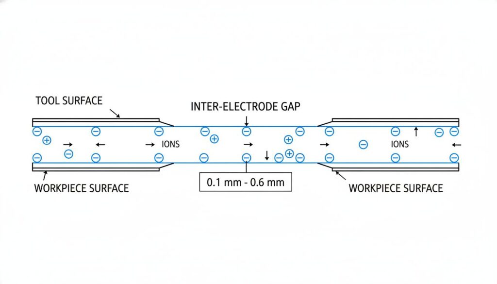
Technical Diagram: A magnified cross-section diagram focusing strictly on the ‘Inter-electrode Gap’. Show the tool surface and workpiece surface separated by a tiny gap labeled ‘0.1 mm – 0.6 mm’. Show ions moving across this gap.
5. Electrolyte Flow Rate
This is how fast the liquid is pumped through the gap.
- Requirement: It must be fast (high velocity).
- Why? If the liquid moves too slowly, the sludge will build up and block the electricity. It needs to rush through to keep the area clean.
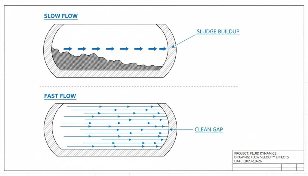
Technical Diagram: A technical illustration showing the ‘sludge’ building up if the flow is slow, versus a clean gap when the flow is fast. Use arrows to indicate velocity.
Final Challenge:
Imagine you increase the **Current** but you make the **Gap** too big. What do you think will happen to the accuracy of your cut?
