Hydraulics is the science of moving liquids to do work. Imagine trying to lift a car with your bare hands. It is impossible. But with a hydraulic jack, you can do it easily. This lesson explains how a simple hydraulic circuit works, what the parts do, and how energy changes form to create massive power.
The Hydraulic Circuit Diagram
To understand hydraulics, engineers draw maps called circuits. These maps show how oil travels through a machine.
Imagine a loop. The oil starts in a tank, goes through a pump, does some work, and comes back to the tank.
Here is how you would draw the connections for a simple system:
- The Reservoir (Tank): Draw a box at the bottom. This holds the oil.
- The Pump: Draw a circle with a triangle inside pointing out. This pulls oil from the tank.
- The Pressure Gauge: Draw a circle with an arrow inside. Connect this right after the pump to measure the push.
- The Relief Valve: Draw a square with a spring and an arrow. Connect this between the pump line and the tank. This is a safety exit.
- The Directional Control Valve (DCV): Draw three squares side-by-side. This goes after the gauge. It directs traffic.
- The Cylinder: Draw a rectangle with a T-shaped rod inside. Connect the DCV to the two ends of this cylinder.

Technical Figure: A clean, 2D schematic diagram of a simple hydraulic circuit. It must include standard ISO symbols for a Reservoir, Hydraulic Pump, Pressure Relief Valve, Pressure Gauge, 4/3 Directional Control Valve, and a Double-Acting Cylinder. The lines should clearly show the flow path connecting these components.
Why We Use Symbols
Drawing a real pump takes a long time. Drawing a circle is fast. Engineers use these standard symbols so anyone in the world can understand the plan.
If you were designing a secret robot, why would it be better to use standard symbols instead of drawing realistic pictures of every part?
The Team Players: Component Functions
Every part of the team has a specific job. If one player is missing, the system fails.
The Hydraulic Pump (The Heart)
The pump is the heart of the system. It does not create pressure; it creates flow. It sucks oil out of the tank and pushes it into the pipes.
- Analogy: Think of your heart pumping blood to your muscles.
- Function: It moves the liquid.
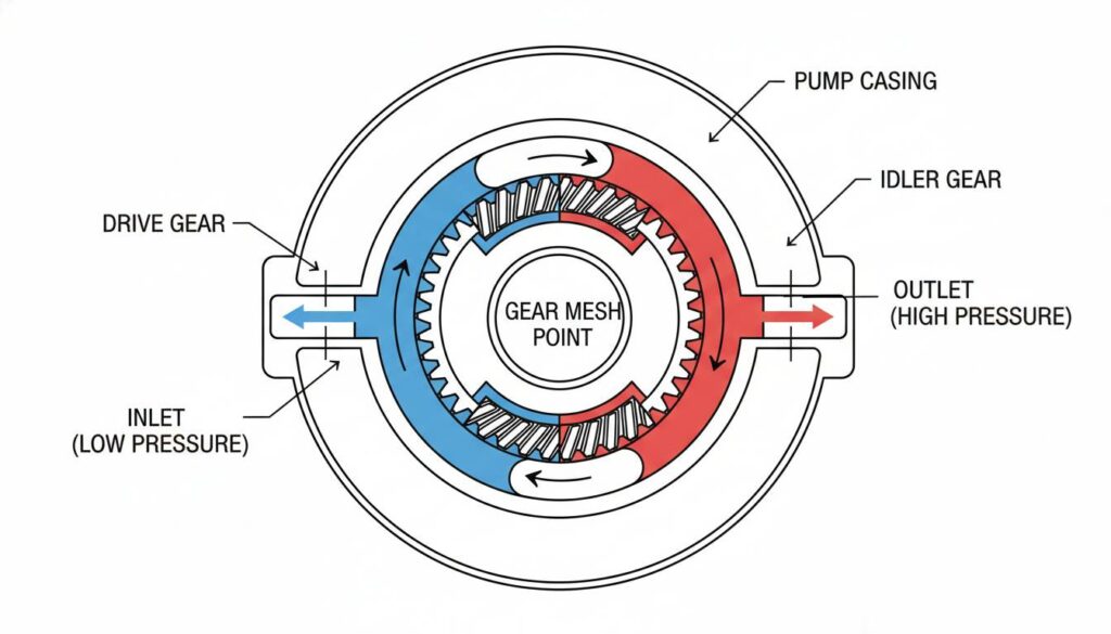
Technical Figure: A cutaway illustration of a hydraulic gear pump. Show two gears meshing together inside a casing, with blue liquid entering one side and red (pressurized) liquid exiting the other side.
The Pressure Relief Valve (The Safety Guard)
Hydraulic systems are very strong. Sometimes, they get too strong. If the pressure gets too high, pipes could burst. The relief valve is a spring-loaded door. If the pressure is too high, the door opens and dumps the oil back into the tank.
- Analogy: The safety valve on a pressure cooker.
- Function: Limits the maximum pressure to keep the system safe.
The Pressure Gauge (The Speedometer)
You need to know what is happening inside the pipes. The gauge has a dial that shows how hard the oil is pushing.
- Analogy: The speedometer in a car or the air gauge on a bicycle pump.
- Function: Visual display of the system’s pressure.
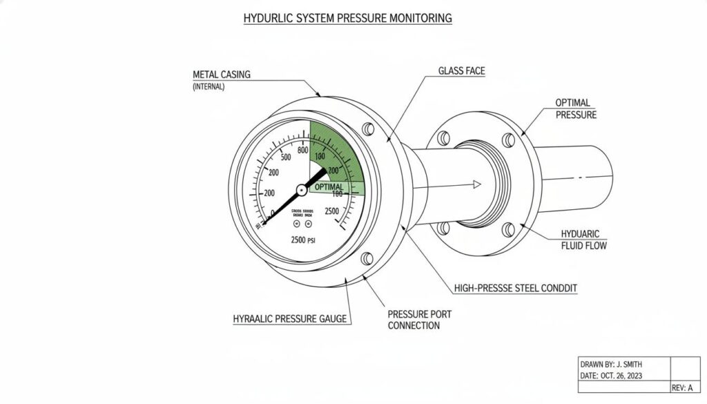
Technical Figure: A close-up photo of a circular hydraulic pressure gauge with a needle pointing to the green zone, attached to a steel hydraulic pipe.
The Directional Control Valve (The Traffic Cop)
The pump pushes oil constantly. But we don’t always want the machine to move. The Directional Control Valve (DCV) tells the oil where to go.
- Lever Forward: Oil goes to the back of the cylinder (extends it).
- Lever Backward: Oil goes to the front of the cylinder (retracts it).
- Lever Center: Oil goes back to the tank (machine stops).
- Function: Controls the start, stop, and direction of the actuator.
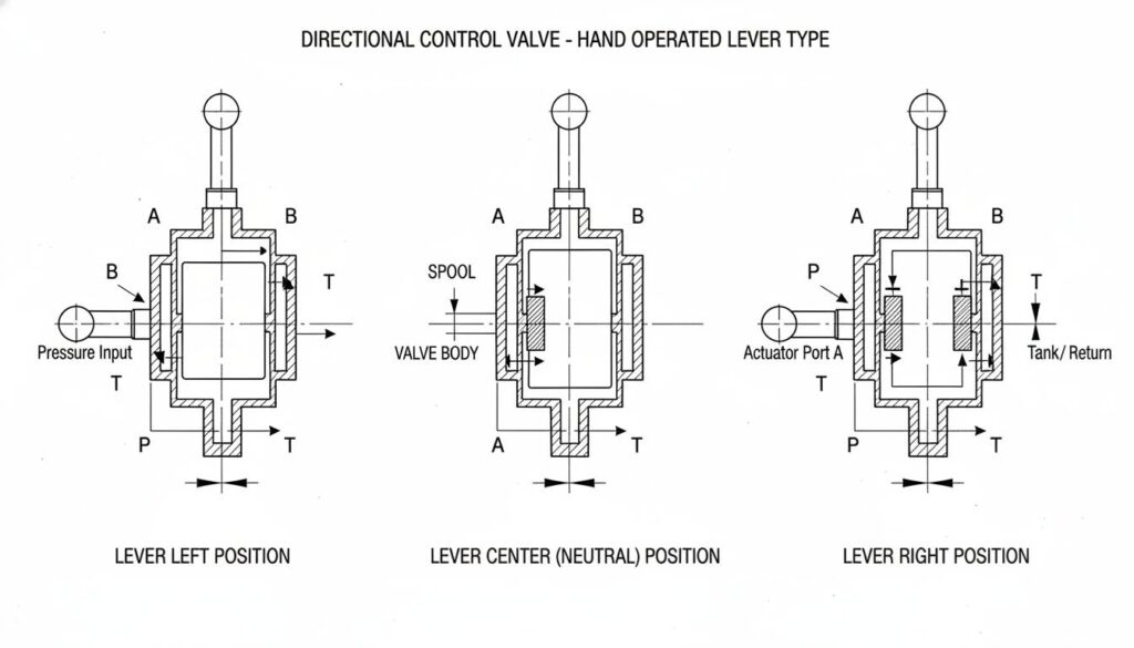
Technical Figure: A 3D diagram of a hand-operated lever valve (Directional Control Valve). Show internal pathways changing as the lever is moved left, center, and right.
The Hydraulic Cylinder (The Muscle)
This is where the work happens. It is a tube with a piston inside. When oil pushes against the piston, the rod moves out. This linear (straight line) motion pushes or lifts the load.
- Analogy: A syringe. When you push the plunger, liquid squirts out. If you pump liquid in, the plunger moves out.
- Function: Converts hydraulic energy back into mechanical force to do work.
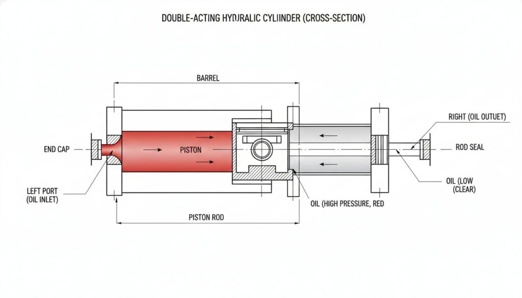
Technical Figure: A cross-section of a double-acting hydraulic cylinder. Show the piston and rod inside the barrel. Highlight red oil entering one side pushing the piston to the right.
Imagine the Relief Valve is stuck closed (it cannot open). What happens to the system if the cylinder hits a wall and stops moving, but the pump keeps running?
Power Transmission and Transformation
How does electricity turn into a lifting force? Energy changes its “costume” three times in a hydraulic system. This is called Transformation.
Step 1: Electrical to Mechanical
It starts with a motor (usually electric or a diesel engine). This motor spins a shaft.
- Transformation: Electrical Energy
 Mechanical (Rotary) Energy.
Step 2: Mechanical to Hydraulic
The spinning motor shaft turns the Pump. The pump pushes the oil. Now the energy is stored in the moving, pressurized liquid.
- Transformation: Mechanical Energy Hydraulic Energy (Flow and Pressure).
Step 3: Hydraulic to Mechanical
The oil travels through the pipes and hits the Cylinder. The pressure pushes the piston. The rod moves out to lift a load.
- Transformation: Hydraulic Energy Mechanical (Linear) Energy.
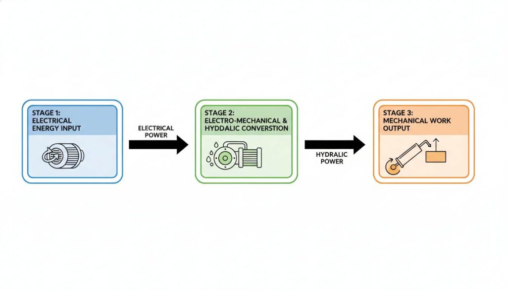
Technical Figure: A colorful flowchart showing the three stages of energy conversion. Stage 1: Electric Motor icon. Stage 2: Hydraulic Pump icon with fluid drops. Stage 3: Hydraulic Cylinder lifting a weight. Arrows connect them showing the flow of power.
Why Do We Do This?
You might ask, “Why not just connect the motor directly to the load?”
The answer is Force Multiplication.
Hydraulics allows us to use a small motor to lift a giant weight. It is like a lever. We trade speed for strength. The oil acts like a solid steel rod that can bend around corners (through hoses) and push with massive force.
A bicycle chain transfers power from your legs to the wheels. How is a hydraulic hose different from a bicycle chain when transferring power?

hello world
Test message. Thank you!