Hydraulics is the science of moving liquids to do heavy work. Imagine trying to lift a car with your bare hands. It is impossible. Now, imagine using a jack. You move a small handle, and the heavy car rises. That is hydraulics in action.
Focus Keyword: Simple Hydraulic System Circuit, Hydraulic Symbols, Basic Hydraulic Elements
It works like a bicycle brake. You squeeze the handle. Fluid moves through a tube. The fluid pushes the brake pads against the wheel.
In engineering, we draw “maps” of these systems called circuits. We use special symbols instead of realistic drawings. This makes the plan easy to read.

Technical Figure: A split screen illustration. On the left, a realistic 3D drawing of a hydraulic log splitter. On the right, a simple 2D schematic diagram of the same machine using standard symbols. Arrows connect the realistic parts to their matching symbols.
The Basic Hydraulic Circuit
A hydraulic system is a loop. Oil leaves a tank, does work, and comes back. To draw this, we use standard symbols. These symbols are the “alphabet” of engineering.
Here is what a complete simple circuit looks like.

Technical Figure: A clean, high-contrast black and white line drawing of a simple hydraulic circuit. It shows a Reservoir at the bottom, a Pump above it, a Pressure Relief Valve branching off, a Directional Control Valve in the middle, and a Hydraulic Cylinder at the top. Lines connect all components.
The Five Key Elements
Every simple hydraulic system needs five main parts to work. Let’s look at each one, its job, and its symbol.
The Reservoir (The Tank)
The reservoir is the storage bucket. It holds the hydraulic oil when it is not being used. It also lets the oil cool down before it goes back to work.
- Analogy: Think of this like the water bottle on a bicycle. It holds the liquid until you need it.
- The Symbol: We draw this as an open box or a rectangle at the bottom of the page.

Technical Figure: A close-up diagram of the ISO symbol for a Hydraulic Reservoir. It looks like a U-shape or an open-topped rectangle. Next to it, a photo of a rectangular metal tank with a filler cap.
The Pump (The Heart)
The pump moves the oil. It takes oil from the tank and pushes it into the system. It creates flow.
- Analogy: This is like your heart. Your heart pumps blood to your muscles. The hydraulic pump pushes oil to the machine’s muscles.
- The Symbol: A circle with a solid black triangle inside. The triangle points out, showing the direction the oil flows.
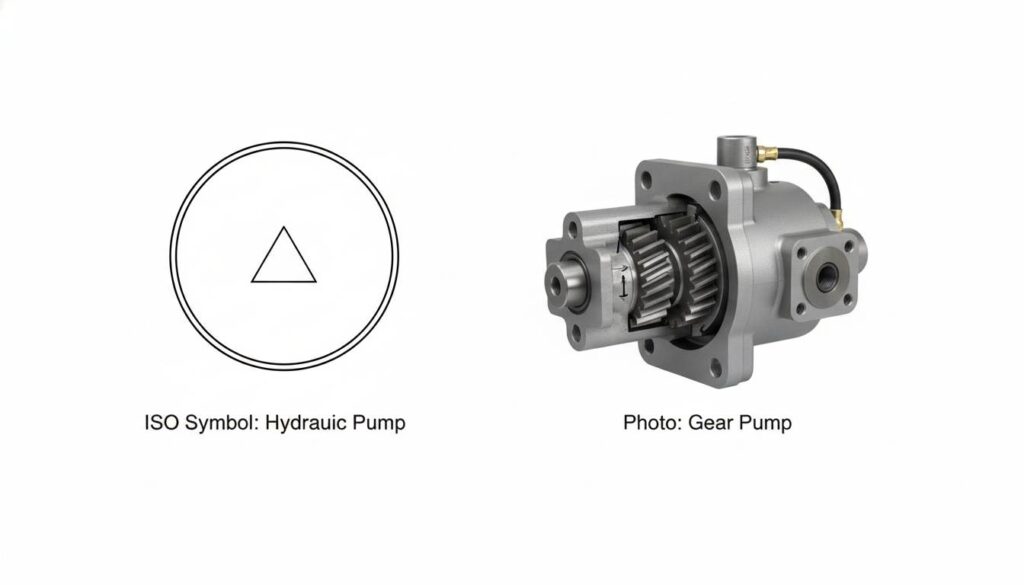
Technical Figure: A close-up diagram of the ISO symbol for a Hydraulic Pump. It is a circle with a small solid black triangle pointing upwards towards the top of the page. Next to it, a photo of a gear pump.
The Pressure Relief Valve (The Safety Guard)
If the pump keeps pushing oil and the oil has nowhere to go, the pipes could burst. The relief valve is a safety door. If the pressure gets too high, this valve opens. It sends the extra oil back to the tank.
- Analogy: Think of a pressure cooker or a tea kettle. When the steam gets too strong, the little whistle lets steam out so the pot doesn’t explode.
- The Symbol: A square box with an arrow inside. The arrow is usually offset, showing the path is normally closed.

Technical Figure: A close-up diagram of the ISO symbol for a Pressure Relief Valve. It shows a square with an arrow that is disconnected from the line, indicating it is normally closed, with a spring symbol on one side.
Think About It:
Why do we need a Relief Valve? What would happen to a garden hose if you plugged the end with your thumb but left the tap running full blast?
The Directional Control Valve (The Traffic Cop)
The pump pushes oil constantly. But we need to tell the oil where to go. Do we want the machine to push out? Or pull back? The Directional Control Valve (DCV) steers the oil.
- Analogy: This is like a railroad switch. It changes the track so the train goes left or right.
- The Symbol: A set of squares side-by-side. Inside the squares are arrows showing where the oil flows.
Technical Figure: A close-up diagram of the ISO symbol for a 4/3 Directional Control Valve. It consists of three squares side-by-side containing crossing and straight arrows.
The Actuator (The Muscle)
This is the part that actually does the work. In a simple system, this is usually a cylinder. The oil pushes a piston inside a tube. The piston moves out to push something.
- Analogy: This is like the plunger in a syringe. When you push the liquid, the plunger moves.
- The Symbol: A rectangle with a T-shaped bar inside it. The bar represents the piston and rod.

Technical Figure: A close-up diagram of the ISO symbol for a Double Acting Cylinder. It is a rectangle representing the barrel, with a T-shape inside representing the piston and rod. Two lines enter the rectangle, one on each side of the piston.
How the System Works
Now we connect the parts. Here is the journey of the oil:
- Start: The Pump sucks oil from the Reservoir.
- Flow: The pump pushes the oil to the Control Valve.
- Decision: You pull a lever on the Control Valve. This opens a path.
- Action: The oil flows into the Cylinder. It pushes the piston. The machine lifts the load.
- Return: The used oil on the other side of the piston is pushed out. It travels through the valve and back into the Reservoir.
If the load is too heavy to lift, the pressure builds up. The Relief Valve pops open. The oil skips the cylinder and goes straight back to the tank. This keeps everything safe.
Technical Figure: A sequential diagram with arrows showing the flow of red liquid (oil). Step 1: Oil leaves tank. Step 2: Oil goes through pump. Step 3: Oil goes through valve. Step 4: Oil enters bottom of cylinder, pushing the rod up.
Check Your Understanding:
If the hydraulic pump stops working (the heart stops), can the cylinder (the muscle) still move the load? Why or why not?
