
Fundamentals of Fluid Power
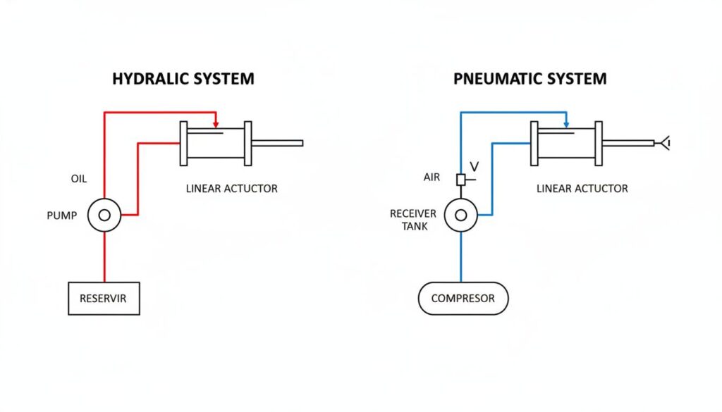
Engineering Figure 1
A split technical diagram comparing a basic hydraulic system and a pneumatic system side-by-side. The hydraulic side shows a reservoir, pump, and oil lines in red. The pneumatic side shows a compressor, receiver tank, and air lines in blue. Both connect to a linear cylinder actuator.
Definition and Scope
Fluid power is the technology that deals with the generation, control, and transmission of power using pressurized fluids. It is a sub-discipline of fluid mechanics and is distinct from fluid transport (which focuses on moving fluids from one location to another). Fluid power systems are classified into two primary domains:
- Hydraulics: Uses liquids (mineral oils, water-based emulsions, or synthetics) to transmit power.
- Pneumatics: Uses gases (usually compressed air) to transmit power.
Comparison of Fluid Power Systems
| Feature | Hydraulic System | Pneumatic System |
| Working Fluid | Incompressible Liquid (Oil) | Compressible Gas (Air) |
| Operating Pressure | High (up to 700 bar or more) | Low (typically 5 to 10 bar) |
| Power-to-Weight Ratio | Extremely High | Moderate |
| Accuracy | High precision due to fluid incompressibility | Lower precision due to air compressibility |
| Lubrication | Self-lubricating | Requires mist lubrication (FRL unit) |
| Application | Heavy lifting, press work, earth movers | Automation, robotics, dentistry, packaging |
Advantages of Fluid Power
- Multiplication of Force: Small input forces can generate massive output forces.
- Infinite Speed Control: Variable speed is easily achieved by controlling flow rates.
- Overload Protection: Pressure relief valves provide automatic protection against system damage.
- Reversibility: Actuators can stop and reverse direction almost instantly.
Critical Inquiry Challenge
Consider a scenario where a hydraulic system and a pneumatic system are both designed to exert a force of 10 kN. Why is the bulk modulus of the fluid the deciding factor when the application requires holding the load in a precise, fixed position for an extended duration without mechanical locking?
Theoretical Foundations and Governing Laws

Engineering Figure 2
A schematic diagram illustrating Pascal’s Law using a hydraulic jack. Two pistons of different areas (A1 small, A2 large) are connected by a fluid. A downward force F1 on A1 creates an upward force F2 on A2. Mathematical labels P = F1/A1 = F2/A2 are visible.
Pascal’s Law
The fundamental principle of fluid power is Pascal’s Law, which states that pressure applied to a confined fluid at rest is transmitted undiminished in all directions and acts with equal force on equal areas and at right angles to them.

Where:
 = Pressure (
 or
or  )
)- = Force (
 )
) - = Area (
 )
)
In a hydraulic lever system:
Continuity Equation
This equation relates to the conservation of mass in a flowing fluid. For an incompressible fluid, the flow rate remains constant throughout the system.

Where:
- = Volumetric flow rate (
 )
)  = Velocity of fluid (
 )
)- = Cross-sectional area of the pipe ()
Bernoulli’s Principle
Bernoulli’s equation represents the conservation of energy in a flowing fluid. It states that the sum of pressure energy, kinetic energy, and potential energy per unit weight is constant.
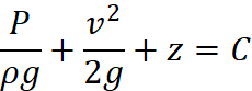
Where:
 = Pressure head
 = Velocity head
 = Elevation head
Hydraulic Power Calculation
The theoretical power required to drive a pump or the power output of an actuator is defined by the product of pressure and flow rate.

In practical engineering units:

Critical Inquiry Challenge
In a hydraulic system, the Continuity Equation dictates that velocity increases as pipe diameter decreases. However, Bernoulli’s principle suggests that as velocity increases, pressure decreases. If a restriction (orifice) is introduced to control flow, how does the resulting pressure drop across the orifice actually generate heat, and how does this relate to the conservation of energy in a non-ideal, viscous fluid?
System Architecture and Key Components
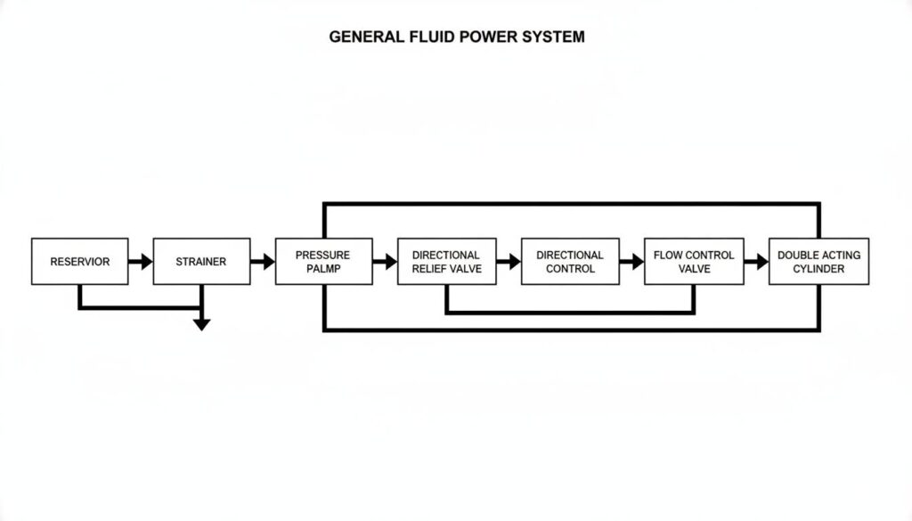
Engineering Figure 3
A block diagram of a general fluid power system layout. Arrows indicate flow direction: Reservoir -> Strainer -> Pump -> Pressure Relief Valve -> Directional Control Valve -> Flow Control Valve -> Double Acting Cylinder. Return lines go back to the reservoir.
1. Prime Mover and Power Generation
- Electric Motor / IC Engine: Provides mechanical energy to the pump.
- Hydraulic Pump: Converts mechanical energy into hydraulic energy (pressure and flow).
- Types: Gear pumps (external/internal), Vane pumps (balanced/unbalanced), Piston pumps (axial/radial).
- Air Compressor: Used in pneumatics to compress air.
2. Control Valves
Valves regulate the pressure, direction, and flow rate of the fluid.
Directional Control Valves (DCV)
Control the start, stop, and direction of fluid flow.
- Designation: Number of ports / Number of positions (e.g., 4/3 DCV).
- Actuation: Manual lever, solenoid, pilot-operated.
Pressure Control Valves (PCV)
Protect the system and control force.
- Pressure Relief Valve: Limits maximum system pressure.
- Pressure Reducing Valve: Maintains a lower pressure in a sub-circuit.
- Sequence Valve: Directs flow to a secondary circuit after a set pressure is reached.
Flow Control Valves (FCV)
Control the speed of the actuator by regulating flow rate (Q)
- Needle Valve: Variable restriction.
- Pressure Compensated FCV: Maintains constant flow regardless of load pressure changes.
3. Actuators
Convert fluid energy back into mechanical energy.
- Linear Actuators (Cylinders):
- Single Acting: Power in one direction, spring or gravity return.
- Double Acting: Power in both extension and retraction.
- Rotary Actuators (Motors): Continuous rotational motion (Gear, Vane, or Piston motors).
4. Fluid Conditioning and Accessories
- Reservoir (Hydraulics): Stores fluid, dissipates heat, allows air separation.
- FRL Unit (Pneumatics): Filter, Regulator, Lubricator unit used to condition compressed air.
- Filters: Remove particulate contamination (Suction, Pressure, and Return line filters).
- Accumulators: Store hydraulic energy, dampen pulsations, and compensate for leakage.
Critical Inquiry Challenge
A “Regenerative Circuit” connects the rod end of a double-acting cylinder directly to the pressure line along with the cap end. While this increases the extension speed significantly, it drastically reduces the force capability. Mathematically, why is the force output in a regenerative extension determined solely by the rod area, despite pressure acting on the piston area as well?
Hydraulic Fluids
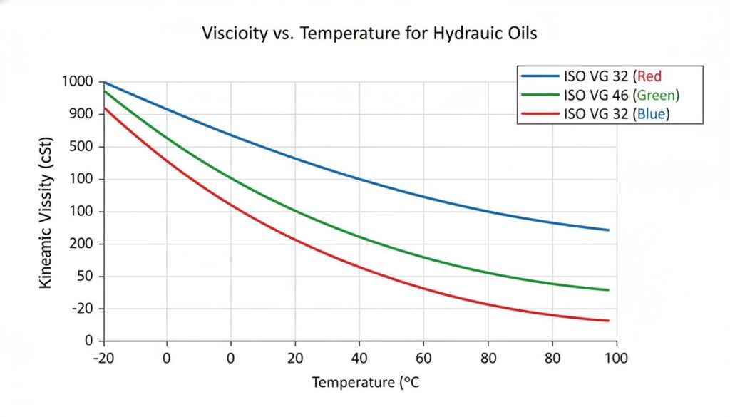
Engineering Figure 4
A technical graph showing Viscosity vs. Temperature curves for different ISO grade hydraulic oils (ISO VG 32, 46, 68). The Y-axis is kinematic viscosity in centistokes (cSt) on a logarithmic scale, and the X-axis is temperature in degrees Celsius.
Primary Functions
- Power Transmission: The medium for transferring energy.
- Lubrication: Reduces friction and wear between moving parts (e.g., pump vanes, valve spools).
- Sealing: Viscosity helps seal clearances between mating parts.
- Cooling: Carries heat generated by friction and pressure drops to the reservoir.
Critical Properties
- Viscosity: A measure of the fluid’s resistance to flow.
- Too High: High resistance, increased friction, pump cavitation, sluggish operation.
- Too Low: Excessive leakage, poor lubrication, inability to build pressure.
- Viscosity Index (VI): Indicates how viscosity changes with temperature. A high VI means viscosity remains relatively stable across temperature changes.
- Demulsibility: The ability of the fluid to separate from water.
- Oxidation Stability: Resistance to chemical breakdown under heat and pressure.
- Flash Point: The lowest temperature at which fluid vapor ignites.
Fluid Types
- Petroleum-based (Mineral Oil): Most common, cost-effective, good lubrication.
- Synthetic Fluids: Phosphate esters, used for fire resistance or extreme temperatures.
- High-Water Content Fluids (HWCF): Fire-resistant, but lower lubrication capability.
Critical Inquiry Challenge
Cavitation in hydraulic pumps is often attributed to low inlet pressure causing the fluid to vaporize. However, “Air Release” and “Foaming” are distinct fluid properties related to entrained air, not vapor. How does the presence of entrained air bubbles specifically exacerbate the damage caused by pseudo-cavitation (aeration) compared to true vaporous cavitation?
